BC_SYMMETRY
Boundary conditions
plane, csysid${}_1$, csysid${}_2$, csysid${}_3$, $tol$
Parameter definition
Description
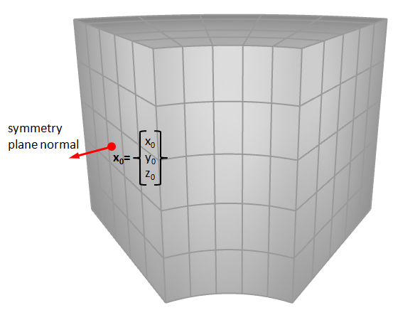
This command defines up to three symmetry planes at $x$, $y$ or $z=0$ or at the origin of specified coordinate systems. When referring to a local coordinate system, the symmetry plane normal is defined as the local x-direction of the coordinate system. The normal direction of the nearest element face is taken as symmetry plane normal in case the local x-direction has not been explicitly defined in the coordinate system command.
Appropriate boundary conditions are automatical applied to nodes located on a symmetry plane. External faces on a symmetry plane are excluded from the contact.
Symmetry conditions are also applied to the boundary of the global particle domain (see PARTICLE_DOMAIN).
Symmetry planes can also be used as rigid frictionless walls, that nodes can not penetrate.
Example
Symmetry plane
The following commands apply symmetry boundary conditions on a surface. A point on the symmetry plane is defined through a local coordinate system with ID = 20. The normal of the nearest element face is used as symmetry plane normal.