INITIAL_MATERIAL_DIRECTION_WRAP
Initial conditions
"Optional title"
coid, entype, enid
$x_0$, $y_0$, $z_0$, $\hat{u}_x$, $\hat{u}_y$, $\hat{u}_z$, $\alpha$
Parameter definition
Description
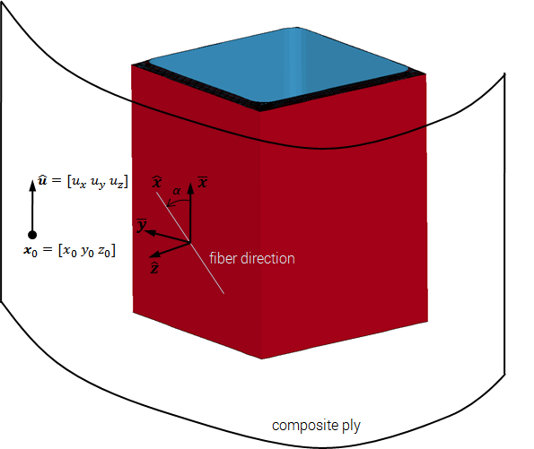
This command is used to define local material directions in anisotropic materials such as fiber composites. The user defines the location and orientation of a "ply" in space. This ply is then wrapped around the component.
Note that models with more than one element in thickness direction require special consideration. For such models the wrapping algorithm requires a mesh with elements that are larger in-plane than in thickness direction.
The ply first needs to be projected onto the component. This projection generates intermediate in-plane directions $\bar{\mathbf x}$ and $\bar{\mathbf y}$.
$\displaystyle{ \bar{\mathbf y} = \frac{\hat{\mathbf z} \times \hat{\mathbf u}}{\vert \hat{\mathbf z} \times \hat{\mathbf u} \vert}}$
$\displaystyle{ \bar{\mathbf x} = \bar{\mathbf y} \times \hat{\mathbf z}}$
where $\hat{\mathbf z}$ is the local face surface normal direction. The local fiber direction $\hat{\mathbf x}$ and the orthogonal direction $\hat{\mathbf y}$ can now be defined by rotating the intermediate directions with the angle $\alpha$.
$\displaystyle{ \hat{\mathbf x} = \cos (\alpha) \bar{\mathbf x} + \sin (\alpha) \bar{\mathbf y}}$
$\displaystyle{ \hat{\mathbf y} =-\sin (\alpha) \bar{\mathbf x} + \cos (\alpha) \bar{\mathbf y}}$