
CONTACT
Contact and tied interfaces
"Optional title"
coid, accuracy_level, accuracy_edge
entype${}_1$, enid${}_1$, entype${}_2$, enid${}_2$, $\mu$, $pfac$, $t_{beg}$, $t_{end}$
merge, $\xi$, gid${}_0$, gid${}_1$, $\delta_{0}^{offset}$, $\delta_{0}^{max}$, $\delta^{edge}$
fid${}_{wear1}$, fid${}_{wear2}$, fid${}_{thermal}$, $\alpha_{edge}$, one_way, no_internal, $\sigma_{stick}$, fric_heat
Parameter definition
Description
This command defines contact between two surfaces (here referred to as Surface 1 and Surface 2). The overlap between surfaces in contact is estimated through numerical integration. The user can specify different levels of accuracy for this numerical integration. Default value (accuracy_level=2) is a good choice for most situations. The low accuracy option is generally only recommended in situations where the total memory requirement of the model needs to be reduced.
The contact treatment is by default symmetric. The input order of Surface 1 and Surface 2 is arbitrary, unless one_way=1. If one_way=1, Surface 2 alone is used to define the contact surface. That is, in a case without friction all forces will then be perfectly perpendicular to Surface 2.
A value for the penalty stiffness ($pfac$) or a unit system (see UNIT_SYSTEM) must be defined in the command file. A unit system based stiffness is computed if $pfac$ has not been defined by the user. It is individual for each part ID and it calculated according to:
$\displaystyle{ pfac = \frac{K}{L_{min}} \times \min \left(1 + \left( \frac{v_{max}}{100} \right)^2,100 \right) } \,\,\, \mathrm{[Pa/m]}$
where $K$ is the initial linear bulk modulus, $L_{min}$ is the characteristic size of the smallest element in the part and $v_{max}$ is the highest initial velocity in the model. For rigid bodies (who do not have a bulk modulus) the penalty stiffness is defined as:
$\displaystyle{ pfac = 10^{13} \times \min \left(1 + \left( \frac{v_{max}}{100} \right)^2,100 \right) } \,\,\, \mathrm{[Pa/m]}$
Assume that two faces are in contact. Face A belongs to a part with penalty stiffness $pfac_A$ and face B belongs to a part with penalty stiffness $pfac_B$. In such case the used penalty stiffness $pfac$ is the minimum of the two values.
$\displaystyle{ pfac = \min (pfac_A, pfac_B)}$
$\delta_{edge}$ can be used in situations where elements undergoing large deformations are sliding against contact surfaces with sharp edges. It should only be used if necessary in order to prevent failing contacts, as it might lead to a certain degree of energy errors.
The calculated wear (optional) does not affect the simulation results. That is, the wear does not affect the geometry of the surfaces in contact. It is only a quantity that can be visualized in the GUI.
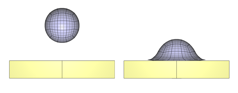
Example
Automatically defined penalty stiffness
This is a complete model of a rubber sphere impacting a block of steel at the velocity $100 \mathrm{m/s}$. The penalty stiffnesses $(pfac_{rubber}=3 \cdot 10^{12}, pfac_{steel} = 1.68 \cdot 10^{13})$ are calculated automatically based on the bulk modulus of the materials, the size of the elements and on the magnitude of the intitial velocities.
Arbitrary friction law
By referring to a FUNCTION, the coefficient of friction can be defined to depend on contact pressure (pres), local coordinate (x, y, z) and on the relative sliding velocity (vtang). The following example defines a transition between a static and a dynamic coefficient of friction.