type
Parameter definition
Variable | Description |
---|---|
type | Update type |
Description
Optional command to enforce curvilinear update of nodes belonging to rigid bodies.
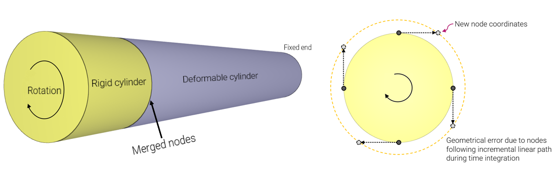
By default (in order to conserve energy) rigid body nodes follow incremental linear paths during time integration, when interacting with deformable bodies. This can lead to significant geometrical errors if both time step size and the rigid body rotations are large.
Example
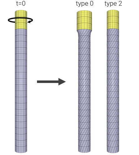
Linear/curvilinear update
Two cylinders, one rigid and one deformable are merged. The free end of the deformable cylinder is fixed and the rigid cylinder is rotating around its central axis, creating torsion. Due to both large time step size and rigid body rotations, a geometrical error is appearing.

One way of solving this problem is to reduce time step size. An alternative approach is to change the update type of the rigid body nodes.

SI
*PARAMETER
%L1 = 1.0, "Length of deformable cylinder"
%L2 = 0.15, "Length of rigid cylinder"
%D = 0.1, "Diameter of cylinders"
%rot = 4*pi, "Rotation at termination"
%tend = 0.01, "Termination time"
%dx = 0.05, "Element size in axial direction"
%type = 2, "Rigid body update type [0, 1 or 2]"
#
# --- TIME and OUTPUT ---
#
*TIME
[%tend]
*OUTPUT
[%tend/5]
#
# --- MESH ---
#
*COMPONENT_CYLINDER
1, 1, [%L1/%dx], 4
0, 0, 0, 0, 0, [%L1], [%D/2]
*COMPONENT_CYLINDER
2, 2, [%L2/%dx], 4
0, 0, [%L1], 0, 0, [%L1+%L2], [%D/2]
*MERGE_DUPLICATED_NODES
P, 1, P, 2, 1e-5
#
# --- MATERIAL ---
#
*MAT_ELASTIC
1, 7800, 210e6, 0.3
*MAT_RIGID
2, 7800
*PART
1, 1, , , 50
2, 2, , , 50
*CHANGE_P-ORDER
ALL, 0, 3
#
# --- BOUNDARY CONDITIONS ---
#
*BC_MOTION
"Fix deformable end"
1
G, 1, XYZ
*GEOMETRY_SEED_COORDINATE
1
0, 0, 0
*BC_MOTION
"Rotation on rigid part"
2
P, 2, Z
D, RZ, 2
*FUNCTION
2
%rot*(t/%tend)
#
# --- RIGID BODY UPDATE ---
#
*RIGID_BODY_UPDATE
[%type]
*END