INCLUDE
Input handling
*INCLUDE
"Optional title"
filename
$sf_x$, $sf_y$, $sf_z$, nid_offset, eid_offset, pid_offset, mid_offset, gid_offset
$x_0$, $y_0$, $z_0$, $x_1$, $y_1$, $z_1$
$\bar{x}_{x}$, $\bar{x}_{y}$, $\bar{x}_{z}$, $\bar{y}_{x}$, $\bar{y}_{y}$, $\bar{y}_{z}$, mirror
"Optional title"
filename
$sf_x$, $sf_y$, $sf_z$, nid_offset, eid_offset, pid_offset, mid_offset, gid_offset
$x_0$, $y_0$, $z_0$, $x_1$, $y_1$, $z_1$
$\bar{x}_{x}$, $\bar{x}_{y}$, $\bar{x}_{z}$, $\bar{y}_{x}$, $\bar{y}_{y}$, $\bar{y}_{z}$, mirror
Parameter definition
Variable
Description
filename
The path and the name of file to be included
$sf_x$, $sf_y$, $sf_z$
Scale factors for nodal coordinates in x, y and z directions
nid_offset
Number to add to all node IDs
eid_offset
Number to add to all element IDs
pid_offset
Number to add to all part IDs
mid_offset
Number to add to all material, damage, EOS and thermal property command IDs
gid_offset
Number to add to all other command IDs
$x_0$, $y_0$, $z_0$
Start point for mesh translation
$x_1$, $y_1$, $z_1$
End point for mesh translation
$\bar{x}_{x}$, $\bar{x}_{y}$, $\bar{x}_{z}$
New direction of x-axis
$\bar{y}_{x}$, $\bar{y}_{y}$, $\bar{y}_{z}$
New direction of y-axis
mirror
Flag to activate mesh mirroring (left handed system where $\bar{\mathbf{z}}=\bar{\mathbf{y}} \times \bar{\mathbf{x}}$)
Description
This command is used to merge a file with the input. The data in the included file can be transformed (optional). A point in the original configuration $\mathbf{x}$ will be moved to location $\mathbf{x}'$ according to:
$\mathbf{x}' = \mathbf{x_1} + \left[ \begin{array}{ccc} \bar{x}_x & \bar{y}_x & \bar{z}_x \\ \bar{x}_y & \bar{y}_y & \bar{z}_y \\ \bar{x}_z & \bar{y}_z & \bar{z}_z \end{array} \right] \cdot \left[ \begin{array}{ccc} sf_x & & \\ & sf_y & \\ & & sf_z \end{array} \right] \left( \mathbf{x} - \mathbf{x_0} \right)$
where:
$\displaystyle{ \bar{\mathbf{z}} = \left\{ \begin{array}{lll} \bar{\mathbf{x}} \times \bar{\mathbf{y}} & : & \mathrm{mirror} = 0 \\ \bar{\mathbf{y}} \times \bar{\mathbf{x}} & : & \mathrm{mirror} = 1 \end{array} \right.}$
Note that the point $\mathbf{x}_0$ in the original configuration will be moved to $\mathbf{x}_1$. This is the base point for both scaling operations and rotations.
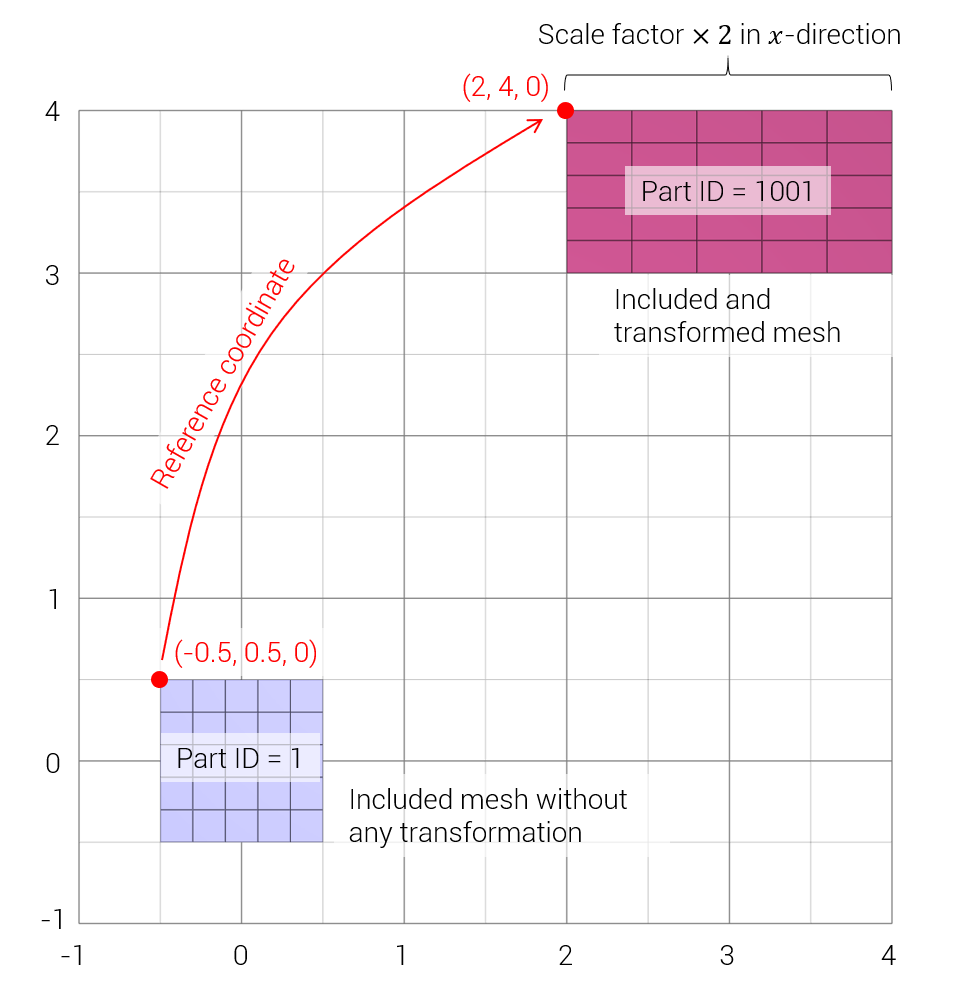
Example
Mesh included twice, with and without offsets
As simple model where the same mesh file mesh.k is included twice, as is and with some offsets.
*UNIT_SYSTEM
SI
*INCLUDE
"without offsets"
mesh.k
*INCLUDE
"with offsets"
mesh.k
2, 1, 1, 1000, 1000, 1000
-0.5, 0.5, 0, 2, 4, 0
*MAT_RIGID
1, 1000
*PART
"without offsets"
1, 1
"with offsets"
1001, 1
*END