"Optional title"
coid, entype, enid, csysid, fid${}_1$, fid${}_2$, fid${}_3$, fid${}_4$
Parameter definition
Variable | Description |
---|---|
coid | Command ID |
entype | Entity type |
enid | Entity ID |
csysid | ID of cylindrical coordinate system |
fid${}_1$ | FUNCTION defining radial displacement of inner surface |
fid${}_2$ | FUNCTION defining radial displacement of outer surface |
fid${}_3$ | FUNCTION defining axial displacement |
fid${}_4$ | FUNCTION defining tangential displacement |
Description
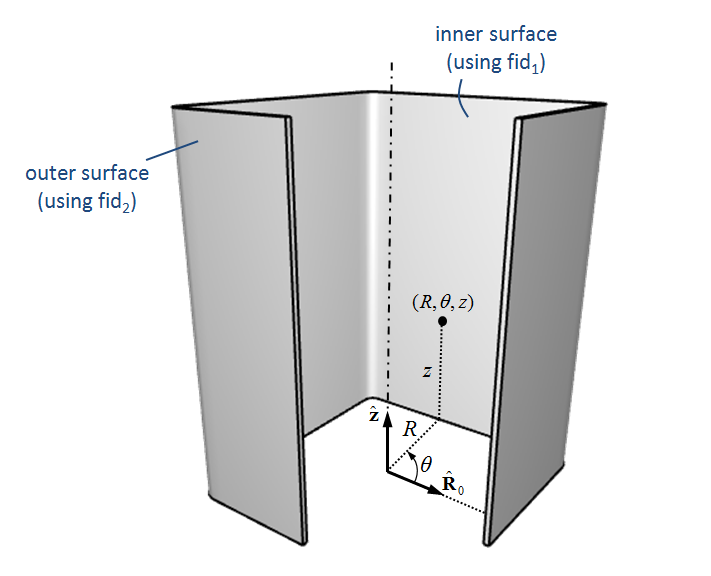
This command is used to transform a mesh. The transformation is expressed as diplacements in cylindrical coordinates $(R,\theta,z)$. $R$ is the radius, $z$ is the axial coordinate and $\theta$ is a circumferential angle ranging from $0^\circ$ to $360^\circ$.
If fid${}_1 \neq$ fid${}_2$ inner and outer surfaces use different radial transformations (see example below). In such situations only nodes on the surface of the body are transformed. Interior nodes are not treated. However, all nodes are transformed in the radial direction if fid${}_1 =$ fid${}_2$.

Example
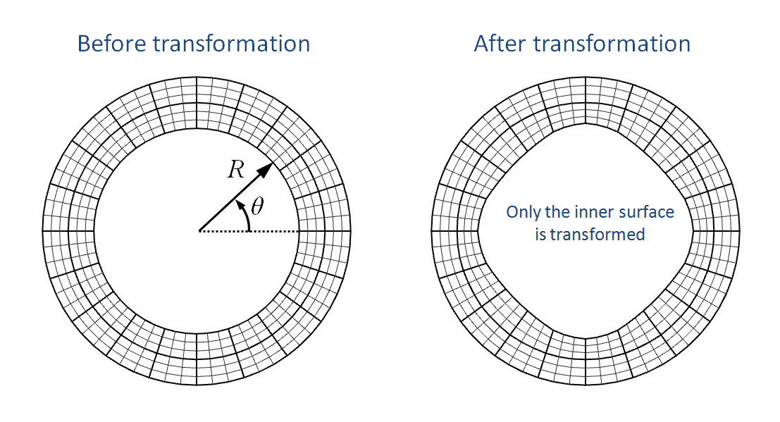
Transform mesh cylindrical - inner surface
Example where only the inner surface is transformed.
H = 0.005 # ring height
R0 = 0.010 # inner radius
R1 = 0.015 # outer radius
dR = 0.0005 # radial distortion
*COMPONENT_PIPE
"ring"
1, 1, 1, 20, 2
0, 0, 0, 0, 0, [%H], [%R0], [%R1]
*CHANGE_P-ORDER
ALL, 0, 3
*SMOOTH_MESH
P, 1, 45.0, 1
*MAT_ELASTIC
1, 7800.0, 210.0e9, 0.3
*PART
"ring"
1, 1
*TRANSFORM_MESH_CYLINDRICAL
1, P, 1, 10, 20
*COORDINATE_SYSTEM_CYLINDRICAL
10, 0, 0, 0
0, 0, 1, 1, 0, 0
*FUNCTION
20
%dR*cos(4*theta)
*END

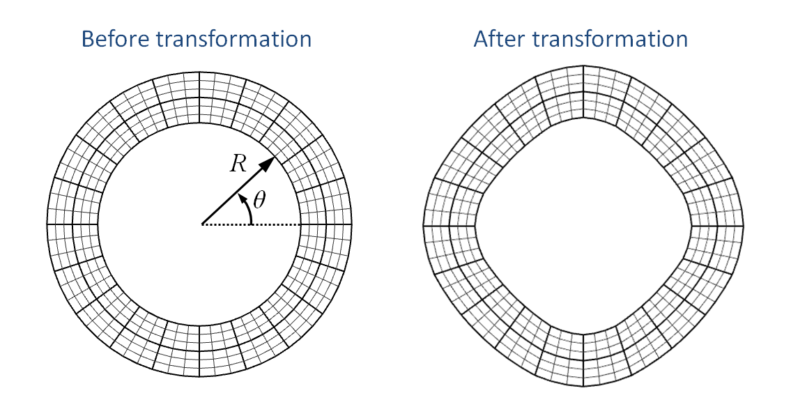
Transform mesh cylindrical - inner and outer surface
Example where the inner and outer surfaces are transformed using the same function. Note that also interior nodes are treated in this situation.
H = 0.005 # ring height
R0 = 0.010 # inner radius
R1 = 0.015 # outer radius
dR = 0.0005 # radial distortion
*COMPONENT_PIPE
"ring"
1, 1, 1, 20, 2
0, 0, 0, 0, 0, [%H], [%R0], [%R1]
*CHANGE_P-ORDER
ALL, 0, 3
*SMOOTH_MESH
P, 1, 45.0, 1
*MAT_ELASTIC
1, 7800.0, 210.0e9, 0.3
*PART
"ring"
1, 1
*TRANSFORM_MESH_CYLINDRICAL
1, P, 1, 10, 20, 20
*COORDINATE_SYSTEM_CYLINDRICAL
10, 0, 0, 0
0, 0, 1, 1, 0, 0
*FUNCTION
20
%dR*cos(4*theta)
*END

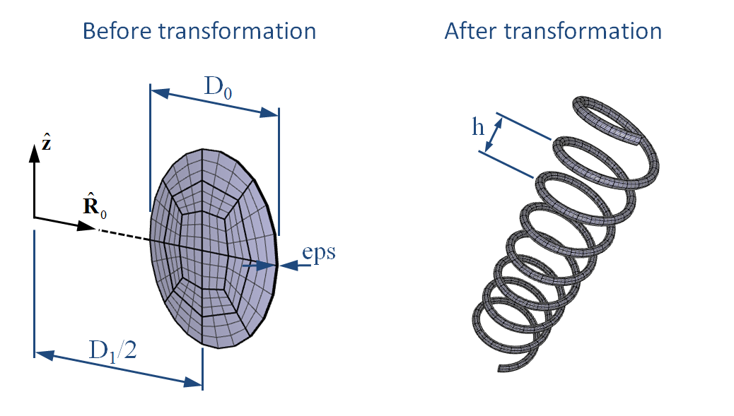
Transform mesh cylindrical - spring
Example using transformation displacements in axial and circumferential directions. A short cylinder is transformed into an object with the shape of a spring.
Ne = 200 # number of elements
D0 = 1.0e-3 # spring thread diameter
D1 = 1.0e-2 # spring coil diameter
Ls = 4.0e-2 # spring length
Nr = 8.0 # number of revolutions
Ps = (%Ls-%D0)/%Nr # spring pitch
eps = 1.0e-5 # initial cylinder length
sf = 2*pi*%Nr/%eps # transformation scale factor
*COMPONENT_CYLINDER
"spring"
1, 1, [%Ne], 2
[%D1/2], 0.0, 0.0, [%D1/2], [%eps], 0.0, [%D0/2]
*CHANGE_P-ORDER
ALL, 0, 3
*MAT_ELASTIC
1, 7800.0, 210.0e9, 0.3
*PART
"spring"
1, 1, 0, 0, 60.0
*TRANSFORM_MESH_CYLINDRICAL
1, P, 1, 10, 0, 0, 20, 30
*COORDINATE_SYSTEM_CYLINDRICAL
10, 0.0, 0.0, 0.0
0.0, 0.0, 1.0
#
# axial displacement
*FUNCTION
20
%Ps*%sf*R*theta/(360.0)
#
# circumferential displacement
*FUNCTION
30
%sf*R*theta
*END
