
SET_GEOMETRY
Sets
*SET_GEOMETRY
"Optional title"
setid
gid${}_1$, ..., gid${}_8$
.
gid${}_{\mathrm{M}}$, ..., gid${}_{\mathrm{N}}$
"Optional title"
setid
gid${}_1$, ..., gid${}_8$
.
gid${}_{\mathrm{M}}$, ..., gid${}_{\mathrm{N}}$
Parameter definition
Variable
Description
setid
Unique geometry set identification number
gid${}_1$, ..., gid${}_8$
Geometry identification number 1 to 8
.
gid${}_{\mathrm{M}}$, ..., gid${}_{\mathrm{N}}$
Geometry identification number M to N
Description
This command defines a set of geometries (see e.g. GEOMETRY_BOX).
Example
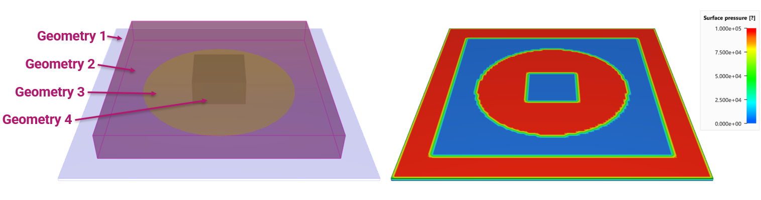
Pressure load on a surface defined with a geometry set
The commands below define a pressure load on square plate. Geometry 1 marks all faces on the top surface of the plate. Geometry 2 is a box. Referring to -2 means that all faces inside the box are removed from the face list. Geometry 3 adds faces inside a cylinder and, finally, Geometry 4 removes faces inside a box.
*COMPONENT_BOX
1, 1, 100, 100, 1
0, 0, 0, 1, 1, 0.01
*MAT_RIGID
1, 7800
*PART
1, 1
# Pressure load defined with geometry set
*LOAD_PRESSURE
1
GS, 1234, 100
*FUNCTION
100
1.0e5
*GEOMETRY_SEED_COORDINATE
1
0.5, 0.5, 0.01
*GEOMETRY_BOX
2
0.1, 0.1, 0, 0.9, 0.9, 0.1
*GEOMETRY_PIPE
3
0.5, 0.5, 0.0099, 0.5, 0.5, 0.0101, 0.3
*GEOMETRY_BOX
4
0.4, 0.4, 0, 0.6, 0.6, 0.1
*SET_GEOMETRY
1234
1, -2, 3, -4
*END