LOAD_DAMPING
Loads
"Optional title"
entype, enid, cid, $\mu$, $c_{dec}$, $sf$, gid
Parameter definition
Description
This command is used to define mass damping and viscous damping for a given subset of the model. If a geometry ID (gid) is defined, then only those nodes/particles located inside the geometry will be damped. The mass damping force $\mathbf{F}_i$ acting on a node $i$ is defined as:
$\displaystyle{ \mathbf{F}_i = \left\{ \begin{array}{rcl} -C \cdot m_i \cdot \mathbf{v}_i & : & \mathrm{when \; moving \; towards \; equilibrium} \\ -sf \cdot C \cdot m_i \cdot \mathbf{v}_i & : & \mathrm{when \; moving \; away \; from \; equilibrium} \end{array} \right. }$
where $C$ is the damping coefficient defined by the CURVE or FUNCTION with ID cid, $m_i$ is the node mass and $\mathbf{v}_i$ is the node velocity. Whether the state is moving towards equilibrium or not is automatically determined by looking at the energy levels.
The viscous damping is defined as an artificial material viscosity (not active for entype=SPH). This viscosity produces an extra, strain rate dependent, stress term $\boldsymbol{\sigma}_\mu$:
$\displaystyle{ \boldsymbol{\sigma}_\mu = \frac{\mu}{c_{dec}} \int_0^t \dot{\boldsymbol{\varepsilon}}(\tau) \cdot \mathrm{e}^{(\tau-t)/c_{dec}} \mathrm{d}\tau }$
Example
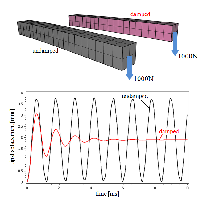
Viscous damping
A complete model of two tip loaded cantilever beams, one with applied viscous damping and one without.
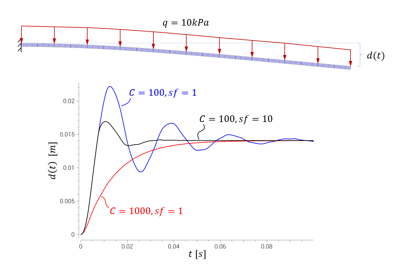
Mass damping and the use of $sf \gt 1$ for faster dynamic relaxation
An elastic cantilever beam is exposed to a static pressure load. Mass damping helps us approach the static equilibrium. Note that FREQUENCY_CUTOFF is applied to increase the critical time step size.